Description
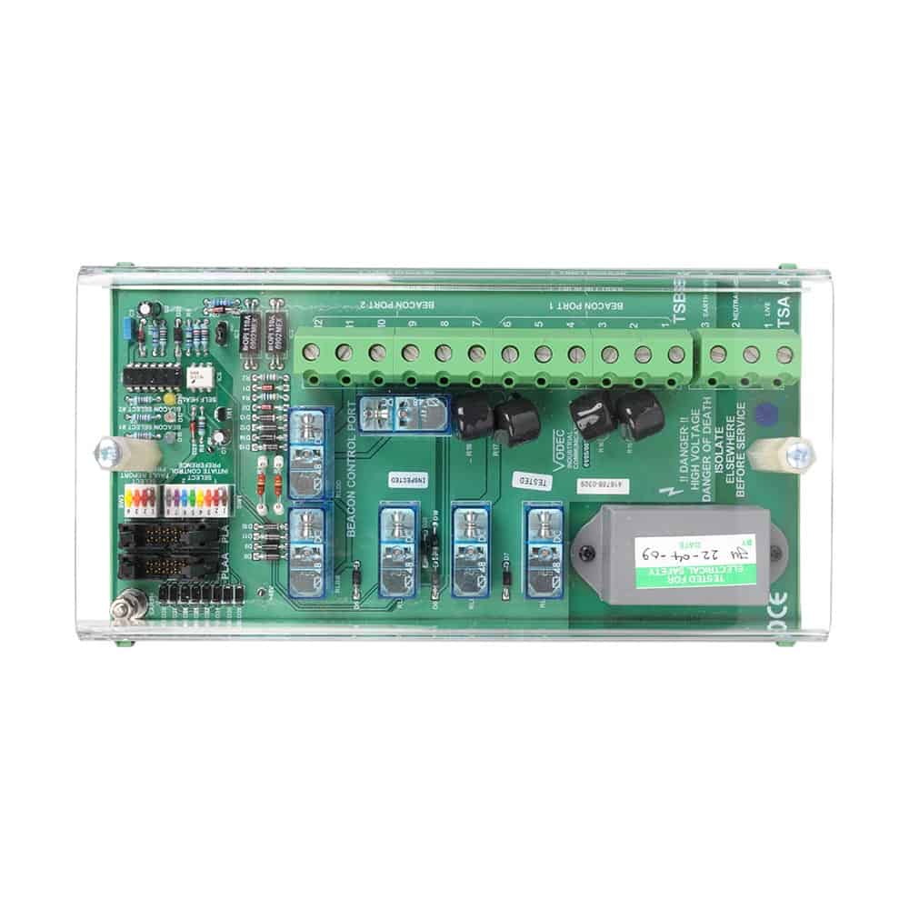
The beacon control port comprises of a compact DIN rail mount snap on/off assembly which houses a single glass fibre printed circuit card. Mains power supply is terminated on to 10 mm² cable conductors. Each Beacon control outlet is discretely fuse protected on board by industry standard cartridge fuse links.
Connection to the host management switch is via a plug in/out flat (ribbon insulation displacement) cable. This cable carries control signal initiation for each port outlet, both for supervisory checks and operation during an alarm or emergency broadcast it also facilitates beacon line monitor “trouble“ status hand shake back to the host system management. Supervision is by momentary application of mains supply to the beacon cable networks initiated by the management switch, correct “end of line“ voltage is sensed by optically coupled devices with resulting go/no go status returned to host management switch. A supervisory cycle is initiated automatically by the switch for 0.25 seconds at 600 second intervals.
Two banks of switches are fitted to the port to enable the commissioning/service engineer to:
- Declare which broadcast condition will initiate which beacon port outlet
- A second switch bank enables the engineer to route the beacon port fault report output to the next available supervisory input on the host VX/AT-M management switch A VX/AT-M switch can manage up to four beacon ports without recourse to additional expansion hardware.
Control and supervisory connectivity is by loop in/out 10 way five ribbon cable which interconnect each port and the host switch.

